How Low-Voltage Motor Circuit Analysis Helps Predict Failures Early
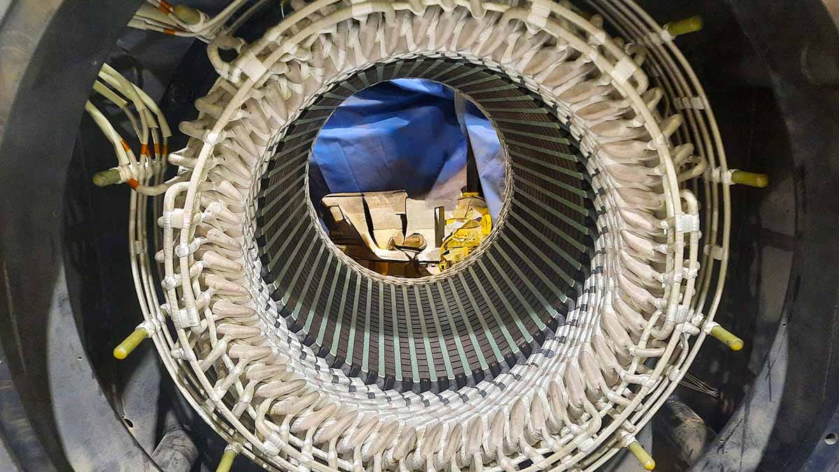
We utilize virtually all testing methods for evaluating industrial and electrical systems for condition and root-cause analysis. Depending on the investigation, we will select either high-voltage or low-voltage motor circuit analysis (MCA).
For this article, we will discuss low-voltage MCA, which is not a reference to the voltage rating of the electric machine being tested. The output of these types of instruments is generally under 10 Vac with output frequencies under 2 kHz, but the applications span all machine sizes and voltages.
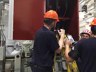
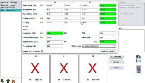
While there are high-voltage MCA devices, such as the Electrom in Figure 3, these may also have low-voltage tests built in, as shown in Figure 4.
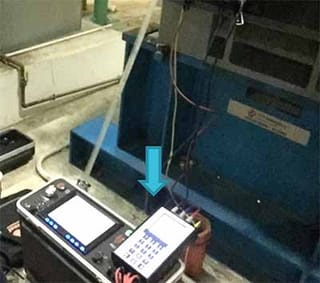
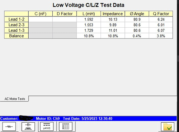
The voltage output of the D12 in Figures 3 and 4 is higher than that of the ATPro system, a significant distinction.
The purpose of low-voltage MCA is to vary the applied frequency to seek imperfections in the insulation system due to material degradation, tracking, or damage, which all impact the inter-turn capacitance.
Between conductors the values will be in inductance (milli-Henries, mH), impedance in ohms (Z), phase angle which identifies the purity of the capacitance (measure of the time relationship between voltage and current), I/F which is the impact on the circuit when the applied frequency is doubled, Q-factor which is the quality of the material, and then the insulation to ground and related capacitance and dissipation factor.
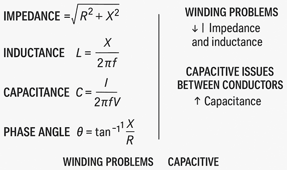
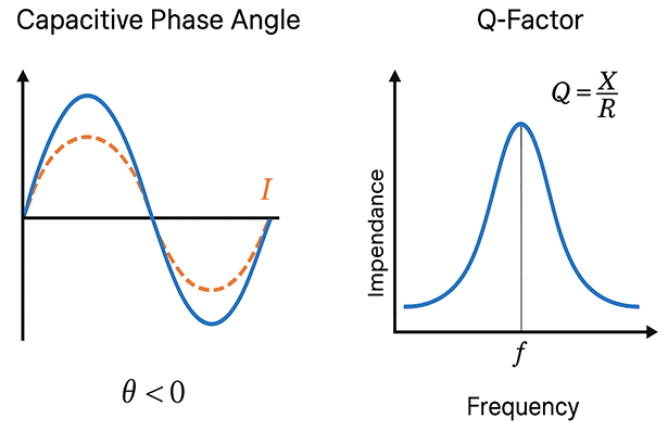
When dealing with a near-perfect sine wave produced by test instruments at different frequencies, the effects caused by variations in the capacitance of the insulation system can be determined. This does not mean that the insulation system must be failed, destroyed, or have a direct short; however, as the insulation system degrades in small areas or overall, the results in each phase change.
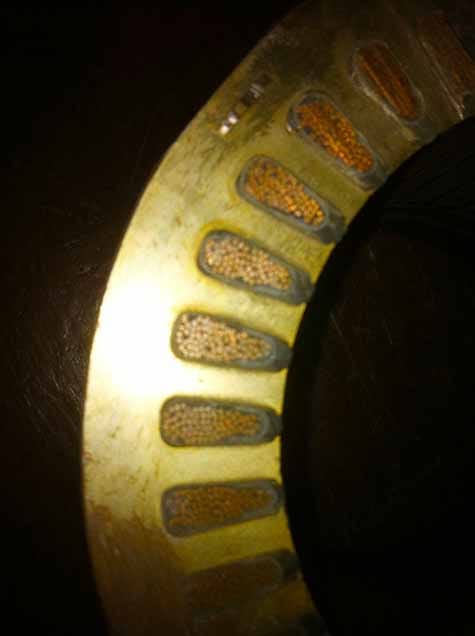
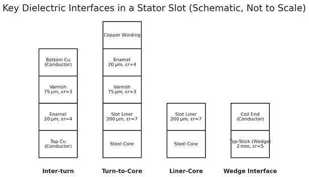
Figure 7 is a cutaway of a winding showing a random-wound motor cutaway. Each of the materials has a slightly different set of electrical properties. Figure 8 shows the averaged and estimated interfaces between the materials in Figure 7 based on the supplied data.
If we assume that the particular machine is either operating at a voltage where partial discharge can occur over a period of time (i.e., >6kV) or for a short period of time at values under 6kV.
Alternatively, for the cutaway, if the motor is on an inverter or variable frequency drive, then PD can occur even at lower voltages due to fast rise-time voltages. The stages of failure in these instances, excluding high potential between odd turns, crossovers, and small gaps or voids, are illustrated in Figure 9.
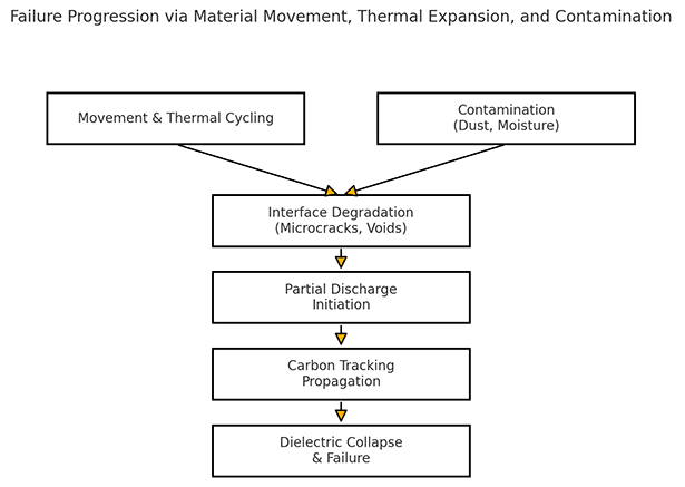
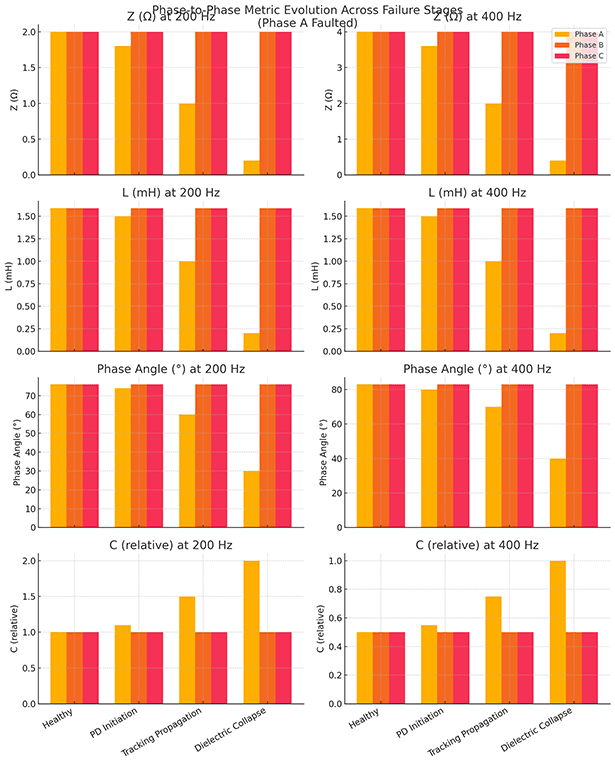
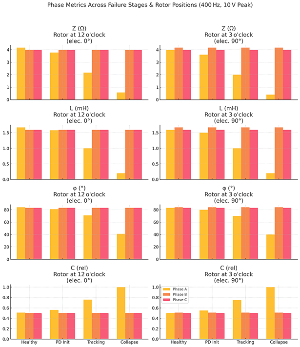
Figure 10 represents data at 200 Hz and 400 Hz as the Figure 9 failure progresses, assuming multiple turns in Phase A are involved in the degradation. This assumes no interaction with a rotor.
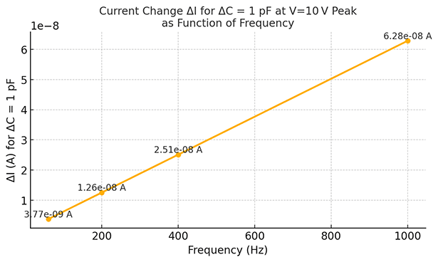
The low voltage and high frequency are important for sensitivity, as shown in Figure 11, where lower voltages and higher frequencies result in greater sensitivity to small changes in capacitance within the winding circuit. For the purpose of this article, we are using one pico-Farad for demonstration.
The same type of relationship also occurs in form wound machines and related insulation degradation by any number of causes. One of the considerations in insulation system failure, however, is when the wire is scratched or damaged in a machine.
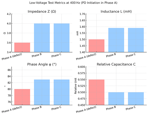
If we introduce a rotor and assume the winding is concentric, such that it represents a small motor with a resulting phase balance, in a healthy machine at 400 Hz, we may see something as shown in Figure 13.
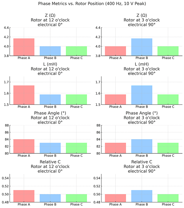
When we introduce the different faults from Figure 10, this relationship, which includes the rotor (Figure 13), can be trended over time, including comparative testing, as shown in Figure 14.
Low-voltage frequency-based testing provides a lighter instrument (portable) with a high degree of accuracy. Over the decades, multiple test devices have been developed that perform this style of testing, with several recognized names, including the ALL-TEST Pro 7.
We have also noted that many traditional high-voltage test devices have been resisting the adoption of these disruptive technologies. However, there are selective times for using either or both technologies, such as the adoption shown with the Electrom D12 and related series.